Mfr Part # DFR1075
FIREBEETLE 2 ESP32-C6 IOT 4MB
DFRobot
License: General Public License Wireless Infrared Proximity DC Motor Microcontrollers Motors Arduino ESP32
If you were lucky enough to see our new booth demo functioning at Maker Faire Rome, you may have asked, “How did this Idea for this demo come about?” This machine was the result of a brainstorming session where the idea to combine two separate projects was brought up. We wanted to combine the Conveyor belt that Aaron Rollens created and combine it with a claw arm from a custom claw machine to create a delivery system. After some further brainstorming, we decided to go beyond the original project idea, and not only did the final design include one conveyor belt, but it had two.
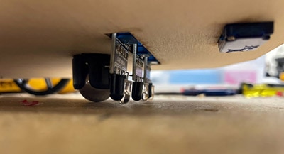
For the system, it works by an item being placed on the back belt. it then travels along the back belt until it runs into a diverter. The diverter then moves the item onto a slide that causes it to slide down onto the front conveyor belt. Once on the bottom belt, the object travels from right to left until it moves in front of an Infrared sensor. The belt then stops, and the claw arm rotates to the front and lowers to pick up the object. Once the object is picked up, the arm raises, rotates over the back belt, and finally places the object onto the back belt to start the journey over again.
Instead of running all the wiring down to a single main board that controlled everything, we decided to add a few neat features for communication. To make sure we complied with all wireless communication standards encountered around the world at the various trade shows we attend, we decided to use ESP-Now as the communication protocol. If you have never heard of ESP-Now, it is a communication protocol that works like Wi-Fi, but it bypasses all the overhead of standard Wi-Fi networking. This means no routers, no IP Addresses, and no handshakes like DHCP or TCP connections. Devices just talk directly to each other by exchanging small and efficient packets.
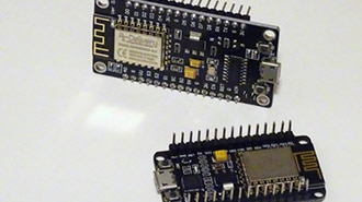
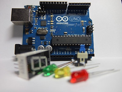
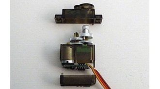
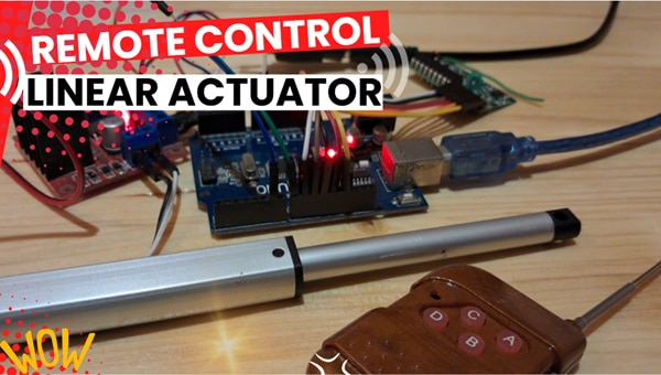
To set up the control system, we ended up using three different control boards. For the main control board, we went with DFRobot’s Firebeetle 2 ESP32-C6. To the main board, we connected a servo for rotation of the claw arm, a custom-designed linear encoder to read the rotation distance, a slide potentiometer to read the height of the claw arm, and an infrared sensor to detect if there was an item at the stopping point on the belt.
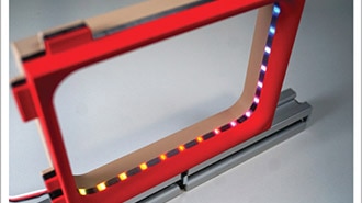
For the Claw arm, we created a custom PCB that mounted right above the claw. The custom board contained a Seeed Studio Xiao ESP32-C3 that was soldered directly to the board. To the custom PCB, we added a connector for a strip of LEDs, the circuitry from the Olimex BB-L298 motor controller for running actuators, and a couple of voltage regulators to provide a 6V output for the servos as well as the linear actuators, and a 5V output for the microcontroller and the LEDs. The claw board controls two linear actuators from DFRobot to lift and lower the arm, as well as a servo that controls opening and closing the claw. There is also a strip of LEDs embedded just above the claw for visual indication. To ensure compatibility with the original machine, the board is designed to accept a 24V power input for the claw arm.
For the third control board, which wasn’t used at the event, we mounted another Seeed Studio Xiao Esp32-C3 in a Hammond box with a single pushbutton that we would use for users to request a giveaway prize. This board just reads the push button and, when pushed, sends a message to the main board to let it know it has been activated. It also uses the LED on the push button to notify when the system is ready for the next input.
For the Claw arm, I adapted some code that I had created for the original claw machine. The original code was user-controlled by a joystick and a series of buttons. After tweaking the code just a bit, I manipulated it so that the main board would function as the user and send simple integers to control the movements. Let’s investigate the code that I ended up using for the final machine on the Claw Board.
Claw Arm Code:
#include <Arduino.h>
#include <ESP32Servo.h>
#include <Adafruit_NeoPixel.h>
#include <esp_now.h>
#include <WiFi.h>

// Define the data structure received via ESP-NOW
typedef struct struct_message {
  char a[32];
  int b; // Corresponds to "Arm Up Down Button"
  int c; // Corresponds to "Claw OpenClose Button"
} struct_message;

// Global variables to hold button states from ESP-NOW
int ArmUpDown = 0;
int ClawOpenClose = 0;

struct_message myData;
struct_message lastMyData; // For anti-spam printing

Servo myservo;
#define PIN_SERVO D0
#define NEOPIXEL_PIN D1

// NeoPixel configuration
#define NUM_PIXELS 40
#define BRIGHTNESS 50

// Linear Actuator pins
#define LINEAR_ACT_PWM 4
#define LINEAR_ACT_DIR1 7
#define LINEAR_ACT_DIR2 21

// Linear actuator PWM configuration
#define LINEAR_PWM_FREQ 1000
#define LINEAR_PWM_RESOLUTION 8
#define LINEAR_PWM_CHANNEL 2

Adafruit_NeoPixel pixels(NUM_PIXELS, NEOPIXEL_PIN, NEO_GRB + NEO_KHZ800);

// --- Servo control variables ---
#define SERVO_OPEN_LIMIT 130
#define SERVO_CLOSE_LIMIT 50

int servoPos = 90;
int servoDirection = 0;
bool isServoActive = false;

unsigned long lastServoUpdateTime = 0;
const unsigned long servoUpdateInterval = 20;

// --- ADDED: Variables for servo detach timeout ---
bool isServoDetaching = false; // A flag to indicate we are in the timeout period
unsigned long servoDetachTimer = 0; // Stores the timestamp when the timeout started
const unsigned long SERVO_DETACH_TIMEOUT = 5000; // 5 seconds in milliseconds

// Other state variables
int linearSpeed = 255;
The libraries that I ended up using were the Arduino library, the ESP32Servo library, the Adafruit_NeoPixel library, the esp_now library, and the Wi-Fi library. For this project, I had to use the ESP32 Servo library because the standard servo library is not compatible with ESP32 boards.
The next thing I had to do was to set up the ESP-Now message structure. To keep the message structure fairly small, I elected to go with a character variable for sending a message within the message, followed by two integers, which would be used to control the lifting and lowering of the linear actuators, and a second variable that was used to control the opening and closing of the claw itself. I then created two variables to transfer the information from the ESP-Now message. ArmUpDown and ClawOpenClose were used exactly how they are called out.
Next, I set up two names for the messages that I would receive. The first is myData, which calls out the most recent message, and a second one called lastMyData, which is used to compare the current message and see if it is the same as the previous message. I’ll dive into these a bit more when we get to the function where the data is read.
Lines 21-23 set up the servo connection. Lines 25-27 set up the NeoPixel string length and brightness, and lines 29-32 set up the linear actuator pin connections. Lines 34-37 set up the linear actuator frequency, resolution, and PWM channel that is used. Line 39 is used for NeoPixel connections, and lastly, line 58 sets up the speed at which the linear actuators are activated.
To make the control of the servo open and close limits, I set up a servo open limit and a servo close limit variable. This makes it easy to adjust how much the claw closes around an item and how far it opens to release that item, making it very adaptable and easily changeable to pick up different items.
Lines 45-55 are all used with the servo. After some testing and burning out a servo on the claw, it was decided to have the claw detach after some time so that it was not continuously powered.
The first function that is set up is OnDataRecv, which controls what happens when ESP-Now communication is received.
// Callback function that only prints when data has changed
void OnDataRecv(const esp_now_recv_info_t *recv_info, const uint8_t *incomingData, int len)
  memcpy(&myData, incomingData, sizeof(myData)).

  if (memcmp(&myData, &lastMyData, sizeof(myData)) != 0) {
    Serial.println("--- ESP-NOW State Changed ---").
    ArmUpDown = myData.b.
    ClawOpenClose = myData.c;

    Serial.println("New Control States:");
    Serial.print("  Arm UpDown:    "); Serial.println(ArmUpDown);
    Serial.print("  Claw OpenClose: "); Serial.println(ClawOpenClose);
    Serial.println("---------------------------");
    Serial.println();

    memcpy(&lastMyData, &myData, sizeof(myData));
  } else {
    ArmUpDown = myData.b;
    ClawOpenClose = myData.c;
  }
}
When a message is received, this function first checks to see if the message is the same as the lastMyData, and if not, it writes the first integer received, in this case myData.b, to the ArmUpDown variable and the second variable, myData.c, to ClawOpenClose. I then added a number of serial print commands so that I could verify that the commands were being received when I was connected to the claw board with my computer while the machine was operating. The last thing this function does is copy the received data over to lastMyData so that it can be compared the next time through.
void setup() {
  Serial.begin(115200);
  delay(1000);
  Serial.println("Starting Claw Machine Receiver...");

  WiFi.mode(WIFI_STA);
  if (esp_now_init() != ESP_OK) {
    Serial.println("Error initializing ESP-NOW");
    return;
  }
  esp_now_register_recv_cb(OnDataRecv);

  ESP32PWM::timerCount[0] = 4;
  myservo.setPeriodHertz(50);
  Serial.println("Servo configured. Awaiting commands to attach.");

  setupLinearActuatorPWM();
  pinMode(LINEAR_ACT_DIR1, OUTPUT);
  pinMode(LINEAR_ACT_DIR2, OUTPUT);
  stopLinearActuator();
  Serial.println("Linear actuator initialized.");

  pixels.begin();
  pixels.setBrightness(BRIGHTNESS);
  pixels.clear();
  pixels.show();
  Serial.println("NeoPixels initialized.");

  Serial.println("Setup complete. Waiting for ESP-NOW commands...");
}
The next section of the code is the setup section. In this section, I began by setting up the serial monitor and printing a message that the board was starting. This was again for troubleshooting purposes. Next, I set up the ESP now communication on lines 87-92. From there, I set up a timer for the servo disconnection time, along with setting up the servo. The next step was setting up the linear actuator. In this section, I also added the stop linear actuator command so that it doesn’t move on startup. After that was completed, I moved on to setting up the NeoPixel strip on lines 104-108. Last, I added another serial print command so I would know that it fully made it through the setup loop.
void loop() {
  if (Serial.available()) {
    char command = Serial.read();
    handleSerialCommand(command);
  }
For the loop portion of the code, I’m going to jump around a bit. First, I’ll show you the portion of the loop and then show the function that is used in that portion of the code. In this case, I set up a function so that I could use the serial monitor to send commands to the board to test the various pieces of the build. The handleSerialCommand function that was used looks like this:
void handleSerialCommand(char command) {
  switch (command) {
    case 's': manualServoTest(); break;
    case 'l': manualLinearTest(); break;
    case 'p': manualPixelTest(); break;
    case 't': Serial.println("Lifting arm to top"); LiftToTop(); break;
    case 'x':
      Serial.println("Stopping all actuators");
      stopLinearActuator();
      if(isServoActive) myservo.detach();
      isServoActive = false;
      isServoDetaching = false;
      pixels.clear();
      pixels.show();
      break;
    default:
      Serial.println("Commands: s(ervo), l(inear), p(ixels), g(ame), t(op), x(stop all)");
      break;
  }
}
When I was testing the various parts of the claw, I could type an “s” into the serial monitor and the servo test function would run, whereas a “l” would cause the manual linear test to run, a “p” would run the pixel test, a “t” would run the linear actuators to the top of their stroke, and if something were to go wrong with the linear actuators “x” was added which caused the linear actuators and the servo to stop essentially becoming an emergency stop option.
Here is a look at those functions:
void manualServoTest() {
  Serial.println("Servo test: Attaching...");
  if (!isServoActive) {
      myservo.attach(PIN_SERVO, 500, 2400);
      isServoActive = true;
  }
  isServoDetaching = false;
  Serial.println("45 -> 90 -> 135 -> 150 -> 90");
  myservo.write(50); delay(1000);
  myservo.write(130); delay(1000);
  myservo.write(50); delay(1000);
  myservo.detach();
  isServoActive = false;
  Serial.println("Servo test complete. Detached.");
}
The manual servo test started by attaching the servo, and then from there would close, open, and then close again. Notice each myservo.write function is followed by a 1-second delay, which is so that the servo can complete its full motion before continuing. If I were to remove these, it would move so fast that the servo would never make it to its destination. The last thing that the test does is detach the servo, so that it is not holding power at its location.
void manualLinearTest() {
  Serial.println("Linear actuator: Extend 2s -> Stop 1s -> Retract 2s -> Stop");
  extendLinearActuator(255); delay(2000);
  stopLinearActuator(); delay(1000);
  retractLinearActuator(255); delay(2000);
  stopLinearActuator();
}
The manual linear test was the next test function. This was set up so that the linear actors would extend for 2 seconds, stop for 1 second, retract for 2 seconds, before stopping to finish the test.
void manualPixelTest() {
  Serial.println("NeoPixel test: Red -> Green -> Blue -> White -> Rainbow");
  pixels.fill(pixels.Color(255, 0, 0)); pixels.show(); delay(500);
  pixels.fill(pixels.Color(0, 255, 0)); pixels.show(); delay(500);
  pixels.fill(pixels.Color(0, 0, 255)); pixels.show(); delay(500);
  pixels.fill(pixels.Color(255, 255, 255)); pixels.show(); delay(500);
  for (int j = 0; j < 256; j++) {
    for (int i = 0; i < NUM_PIXELS; i++) {
      pixels.setPixelColor(i, pixels.ColorHSV(((i * 65536L / NUM_PIXELS) + j * 256) & 65535));
    }
    pixels.show();
    delay(10);
  }
  pixels.clear(); pixels.show();
}
The pixels test ran through a quick test of the pixels by turning them red for ½ second, followed by green for a ½ second, blue for a ½ second, and finally running a rainbow fill before turning off.
These small functions allowed me to confirm that each of the components of the claw arm was functioning properly before moving on to the more complicated action of making it all function together.
Going back to the loop, the next action that was performed was checking the ArmUpDown variable to see what was received and then either extending or retracting the linear actuators to allow the arm to move up or down.
  // --- Linear Actuator Logic (Unchanged) ---
  if (ArmUpDown == -1) {
    retractLinearActuator(255);
  } else if (ArmUpDown == 1) {
    extendLinearActuator(255);
  } else {
    stopLinearActuator();
  }
With ESP-Now, the main board would send three states to control the arm. By sending a 1, the arm would lower, whereas a -1 would cause the arm to raise. If a 0 was sent, the arm would stop moving. The functions for making the linear actuators move are shown below.
void extendLinearActuator(int speed) {
  digitalWrite(LINEAR_ACT_DIR1, HIGH);
  digitalWrite(LINEAR_ACT_DIR2, LOW);
  ledcWrite(LINEAR_ACT_PWM, speed);
}

void retractLinearActuator(int speed) {
  digitalWrite(LINEAR_ACT_DIR1, LOW);
  digitalWrite(LINEAR_ACT_DIR2, HIGH);
  ledcWrite(LINEAR_ACT_PWM, speed);
}

void stopLinearActuator() {
  digitalWrite(LINEAR_ACT_DIR1, LOW);
  digitalWrite(LINEAR_ACT_DIR2, LOW);
  ledcWrite(LINEAR_ACT_PWM, 0);
}
For the functions to make the linear actuators move, one of the direction pins is set low, and the other high, and then a PWM signal is sent to set the speed of the actuators. If the linear actuators need to stop, all that is needed is to set all three of those to LOW or 0. After testing, it was found that the speed of the actuators was relatively slow, so we used full speed on every movement; however, the PWM speed variable was still used in case, at some point, we change the linear actuators for faster ones.
  // --- Incremental Claw Logic with 5-Second Detach Timeout ---

  // 1. Determine direction from ESP-NOW flags
  if (ClawOpenClose == -1) {
    myservo.write(50);
    delay(300);
  } else if (ClawOpenClose == 1) {
    myservo.write(130);
    delay(300);
  } else {
    myservo.write(130);
  }

  // 2. Manage servo state based on user input
  if (ClawOpenClose != 0) {
    // A claw button IS being pressed.
    if (!isServoActive) {
      myservo.attach(PIN_SERVO, 500, 2400);
      isServoActive = true;
      Serial.println("Servo Attached (User Action)");
    }
    if (isServoDetaching) {
      isServoDetaching = false;
      Serial.println("Detach timer cancelled.");
    }
  } else {
    // NO claw button is being pressed.
    if (isServoActive && !isServoDetaching) {
      isServoDetaching = true;
      servoDetachTimer = millis();
      Serial.println("No claw input. Starting 5s detach timer...");
    }
  }

  // 3. Independently check if the detach timer has expired.
  if (isServoDetaching && (millis() - servoDetachTimer >= SERVO_DETACH_TIMEOUT)) {
    myservo.detach();
    isServoActive = false;
    isServoDetaching = false;
    Serial.println("Timeout complete. Servo Detached.");
  }


}
The servo portion of the loop works like the actuator portion. The ClawOpenClose variable is checked, and if the variable is -1, the servo closes. If it happens to be a 1, the servo opens. Instead of stopping, I decided to have the claw fully open if a 0 was sent. This was because if the code were to hiccup a bit and lose its place, the claw would just drop the object if it were holding one to be ready for the next loop.
As you can see, the claw receiver board code is set up to be straightforward without a lot of extras built into it. Now that you’ve seen how the claw board portion of the code works, let's jump into what the code on the main board looks like.
Before we get into the code, I would like to mention that the code on the main board was redesigned many times to get the functionality we wanted. There were many revisions, and I even tried using ClaudeAI to help me with the code, and while that did help, it ended up over-inflating the code with things that I didn’t need to make the machine work. While this isn’t a fully polished code, and I’m sure there are several improvements that could be made, it worked, and that was the important thing.
As I mentioned before, the main board was a DFRobot Firebeetle 2 ESP32-C6, which was mounted on a Terminal Block Board for the Firebeetle 2. The nice thing about this terminal block board is that it accepts 7-24V input power, which means we could power the full machine from a 24V power supply, as the claw also was set up for 24V.
To better understand how the main board controlled everything, let's dig into the code.
#include <Adafruit_NeoPixel.h>
#include <esp_now.h>
#include <WiFi.h>
#include <ESP32Servo.h>
#include <SPI.h>
For the libraries, it is similar to what was used on the Claw arm; however, we also needed to add SPI for the linear encoder.
uint8_t clawBoardMAC[] = { 0x64, 0xE8, 0x33, 0xB6, 0x4F, 0x38 };The next line was where I included the MAC address for the board on the claw arm, which will let the main board know where to send the messages over ESP-Now.
#define LED_PIN 19
#define NUM_LEDS 14
#define LIGHT1_START 0
#define LIGHT2_START 7
#define PIXELS_PER_LIGHT 7
Adafruit_NeoPixel strip(NUM_LEDS, LED_PIN, NEO_GRBW + NEO_KHZ800);
uint32_t GREEN = strip.Color(0, 255, 0, 0);
uint32_t YELLOW = strip.Color(255, 255, 0, 0);
uint32_t RED = strip.Color(255, 0, 0, 0);
uint32_t OFF = strip.Color(0, 0, 0, 0);
Lines 9-18 set up the LEDs on the indication light on the edge of the conveyor, as well as some of the colors that will be used during operation.
// ===== ROTATION SERVO =====
Servo rotationServo;
const int ROTATION_SERVO_PIN = 4;
bool isRotationServoAttached = false;
int pos = 0;
int lastPos = 0;
int midPos = 0;
Lines 20-26 set up the rotation servo by indicating the name that will be called in code, the pin that it is attached to, and 4 variables that will be used to detach the servo, as well as 3 positions that will be used for setting the servo to specific places.
// ===== E-STOP CONFIGURATION =====
const int ESTOP_PIN = 9;
const int ESTOP_DEBOUNCE = 50;
unsigned long lastEstopChange = 0;
bool estopActivated = false;
bool lastEstopState = HIGH;
The next 5 lines are setting up the E-Stop button by including the pin number, a debounce time variable, and three other variables that are used for comparisons.
// ===== MOTOR CONTROL PINS =====
const int ENABLE_A = 2;
const int IN1 = 8;
const int IN2 = 14;
const int ENABLE_B = 3;
const int IN3 = 6;
const int IN4 = 7;
Lines 36-42 set up the Olimex BB-L298 motor controller that we chose to use for the conveyors.
// ===== SENSOR PINS =====
const int LINEAR_ENCODER_PIN = 2;
const int LINEAR_ENCODER_SS = 18;
const int POT_PIN = 5;
const int IR_SENSOR_PIN = 6;
The next group of lines set up the 3 different sensors we were using. Lines 45 and 46 set up the Linear encoder, line 47 called out which pin the slide potentiometer was connected to, and line 48 called out which pin the Infrared sensor was attached to.
// ===== MOTOR SETTINGS =====
const int MIN_SPEED = 80;
const int MAX_SPEED = 255;
const int RAMP_TIME = 750;
const int RAMP_STEP_INTERVAL = 50;

const int SPEED_RANGE = MAX_SPEED - MIN_SPEED;
const int RAMP_STEPS = RAMP_TIME / RAMP_STEP_INTERVAL;
const int SPEED_INCREMENT = max(1, SPEED_RANGE / RAMP_STEPS);
I then set up some variables that would help with the ramping of the motor speeds for the conveyors. The thought process behind this was that the motors would start slower and then ramp up to full speed instead of going full speed as soon as they were turned on.
// ===== CLAW POSITION SETTINGS =====
const int UPPER_BELT_HEIGHT = 665;
const int LOWER_BELT_HEIGHT = 497;
const int MIDDLE_WAIT_HEIGHT = 580;
const int CLAW_SPEED = 150;
const int HEIGHT_TOLERANCE = 10;  // Tolerance for reaching target height

const int SERVO_LOWER_BELT_POSITION = 2200;
const int SERVO_UPPER_BELT_POSITION = 1600;
const int SERVO_SAFE_SPEED = 100;
const int SERVO_STEP_DELAY = 15;
The next grouping of variables was all related to the position and height of the claw arm. To get the upper and lower belt height, I was able to connect to the main board and run the raise and lower test function that I had set up on the claw arm and record the approximate heights needed for both belts. For the front and back position, I was able to disconnect power to the rotation servo and rotate the arm, and take note of the positions on the linear encoder. One thing to note is that during the event, I did run into some issues where the linear encoder was not working correctly, so I ended up only using the servo position to rotate into the positions. I will say that in the future, I will be reimplementing the linear encoder again to make sure that the arm is making it to the desired position. The idea is that if I tell the arm to rotate to “75” it will verify if the rotation actually makes it to position “75” and doesn’t get stuck somewhere in that motion.
// Linear encoder settings
const byte interruptPin = 1;
#define SS_PIN 18
int ClawLatLoc = 0;

// Potentiometer settings
int HeightSensorPin = 5;
int HeightSensorValue = 0;

//INT's for controlling claw arm
// Global variables to hold button states from ESP-NOW
int ArmUpDown = 0;
int ClawOpenClose = 0;

//variable for controlling conveyors
int dir = 1;
int currentState = 0;
int previousState = 0;
unsigned long waveMillis = 0;
unsigned long previousMillis = 0;
unsigned long flashMillis = 0;
int wavePosition = 0;
int flashState = 0;
The last bit of setup involves finishing setting up the Linear encoder, setting up the pin for the linear potentiometer (I noticed this was duplicated at the time of writing this up) and a variable to store the height. Also, it is setting the ArmUpDown and ClawOpenClose variables for transmitting over ESP-Now, and various variables for controlling the lights on the conveyor.
// Define the data structure received via ESP-NOW
typedef struct Claw_command {
  char a[32];
  int b;  // Corresponds to "Arm Up Down Button"
  int c;  // Corresponds to "Claw OpenClose Button"
} struct_message;
// Create a structured object
struct_message ClawCommand;

// Peer info
esp_now_peer_info_t peerInfo;

// Callback function called when data is sent
void OnDataSent(const wifi_tx_info_t *info, esp_now_send_status_t status) {
  // Serial.print("\r\nLast Packet Send Status:\t");
  // Serial.println(status == ESP_NOW_SEND_SUCCESS ? "Delivery Success" : "Delivery Fail");
}
The next group of code was used for the ESP-Now communication. The first part sets up the command that is sent to the claw board. It is then followed by a function for what happens after the packet is sent.
void EncRead() {
  digitalWrite(SS_PIN, HIGH);
  ClawLatLoc = SPI.transfer(0x00);
  digitalWrite(SS_PIN, LOW);
}

void count() {
  EncRead();
}
The next two functions were set up to read the linear encoder and then set up a second function that is used in the interrupt function.
Now that we’ve made it through the setup portion, let's look at some of the functions that are used in the sketch.
void setLight(int startPixel, uint32_t color) {
  for (int i = 0; i < PIXELS_PER_LIGHT; i++) {
    strip.setPixelColor(startPixel + i, color);
  }
}
The first function was setLight and was used to set the lights on the conveyor indicator.
void lowerClaw() {
  while (analogRead(5) > 1700) {
    ArmUpDown = 1;
    // Serial.print("Pot Value:  ");
    // Serial.println(analogRead(5));
    // Format structured data
    strcpy(ClawCommand.a, "Travis's Test message");
    ClawCommand.b = ArmUpDown;
    // Serial.print("  B data: ");
    // Serial.print(ClawCommand.b);
    ClawCommand.c = ClawOpenClose;
    // Serial.print("  C data: ");
    // Serial.print(ClawCommand.c);
    esp_err_t result = esp_now_send(clawBoardMAC, (uint8_t *)&ClawCommand, sizeof(ClawCommand));  // Zero is called out in this page: https://randomnerdtutorials.com/esp-now-one-to-many-esp32-esp8266/

    if (result == ESP_OK) {
      // Serial.println("Sending confirmed");
    } else {
      Serial.println("Sending error");
    }
    delay(20);
  }
  ArmUpDown = 0;
  ClawOpenClose = -1;
  // Format structured data
  strcpy(ClawCommand.a, "Travis's Test message");
  ClawCommand.b = ArmUpDown;
  // Serial.print("  B data: ");
  // Serial.print(ClawCommand.b);
  ClawCommand.c = ClawOpenClose;
  // Serial.print("  C data: ");
  // Serial.print(ClawCommand.c);
  esp_err_t result = esp_now_send(clawBoardMAC, (uint8_t *)&ClawCommand, sizeof(ClawCommand));  // Zero is called out in this page: https://randomnerdtutorials.com/esp-now-one-to-many-esp32-esp8266/

  if (result == ESP_OK) {
    // Serial.println("Sending confirmed");
  } else {
    Serial.println("Sending error");
  }
  delay(20);
}
The second function was lowerClaw. To get this working correctly on the machine, I broke this into a couple of different movements. The first part is that the machine reads the slide potentiometer and sends a message to the claw board to lower the claw until it reaches the desired height of 1700. Once the height is reached, it then sends an arm stop command by sending a 0 over the ArmUpDown variable through ESP-Now, as well as a claw close command by sending a -1 over the clawOpenClose variable.
void raiseClaw() {
  while (analogRead(5) < 2250) {
    ArmUpDown = -1;
    // Format structured data
    strcpy(ClawCommand.a, "Travis's Test message");
    ClawCommand.b = ArmUpDown;
    // Serial.print("  B data: ");
    // Serial.print(ClawCommand.b);
    ClawCommand.c = ClawOpenClose;
    // Serial.print("  C data: ");
    // Serial.print(ClawCommand.c);
    esp_err_t result = esp_now_send(clawBoardMAC, (uint8_t *)&ClawCommand, sizeof(ClawCommand));  // Zero is called out in this page: https://randomnerdtutorials.com/esp-now-one-to-many-esp32-esp8266/

    if (result == ESP_OK) {
      // Serial.println("Sending confirmed");
    } else {
      Serial.println("Sending error");
    }
    delay(20);
  }
  ArmUpDown = 0;
  // Format structured data
  strcpy(ClawCommand.a, "Travis's Test message");
  ClawCommand.b = ArmUpDown;
  // Serial.print("  B data: ");
  // Serial.print(ClawCommand.b);
  ClawCommand.c = ClawOpenClose;
  // Serial.print("  C data: ");
  // Serial.print(ClawCommand.c);
  esp_err_t result = esp_now_send(clawBoardMAC, (uint8_t *)&ClawCommand, sizeof(ClawCommand));  // Zero is called out in this page: https://randomnerdtutorials.com/esp-now-one-to-many-esp32-esp8266/

  if (result == ESP_OK) {
    // Serial.println("Sending confirmed");
  } else {
    Serial.println("Sending error");
  }
  delay(20);
}
The next function is raiseClaw. This function reads the slide potentiometer and continues to send an arm-up command until the arm reaches the desired height of 2250. Once the height is reached, it then sends an arm stop command by sending a 0 over the ArmUpDown variable through ESP-Now.
void clawOpen() {
  ClawOpenClose = 1;
  // Format structured data
  strcpy(ClawCommand.a, "Travis's Test message");
  ClawCommand.b = ArmUpDown;
  // Serial.print("  B data: ");
  // Serial.print(ClawCommand.b);
  ClawCommand.c = ClawOpenClose;
  // Serial.print("  C data: ");
  // Serial.print(ClawCommand.c);
  esp_err_t result = esp_now_send(clawBoardMAC, (uint8_t *)&ClawCommand, sizeof(ClawCommand));  // Zero is called out in this page: https://randomnerdtutorials.com/esp-now-one-to-many-esp32-esp8266/

  if (result == ESP_OK) {
    // Serial.println("Sending confirmed");
  } else {
    Serial.println("Sending error");
  }
  delay(20);
}
The next function was the clawOpen function. This function sends a 1 over the ClawOpenClose variable to the claw board, letting it know to open the claw.
void moveClaw() {
  RotateToFrontBelt();
  delay(500);
  lowerClaw();
  delay(500);
  raiseClaw();
  delay(500);
  RotateToBackBelt();
  delay(500);
  clawOpen();
  delay(500);
}

// ===== ROTATION AND SENSOR FUNCTIONS =====


void EncReadSet() {
  for (int pos = 0; pos <= 10; pos += 1) {
    rotationServo.write(pos);
    delay(15);
  }
  for (int pos = 10; pos >= 0; pos -= 1) {
    rotationServo.write(pos);
    delay(15);
  }
  digitalWrite(SS_PIN, HIGH);
  ClawLatLoc = SPI.transfer(0x00);
  digitalWrite(SS_PIN, LOW);
}

void RotateToFrontBelt() {
  for (pos = lastPos; pos <= 180; pos += 1) {
    rotationServo.write(pos);
    Serial.println(pos);
    delay(15);
    // lastPos = pos;
    if (pos > 178 ) {
      lastPos = pos;
      break;

    }
  }
}

void RotateToBackBelt() {
  for (pos = lastPos; pos >= 0; pos -= 1) {
    rotationServo.write(pos);
    Serial.println(ClawLatLoc);
    delay(15);
    if (pos < 2) {
      lastPos = pos;
      break;
    }
  }
}

void RotateToMid() {
  for (pos = lastPos; pos <= 180; pos += 1) {
    rotationServo.write(pos);
    delay(15);
    if (ClawLatLoc < 105) {
      lastPos = pos;
      break;
    }
  }
}

void  arm() {
  digitalWrite(IN1, LOW);
  digitalWrite(IN2, LOW);
  digitalWrite(ENABLE_A, LOW);

  digitalWrite(IN3, LOW);
  digitalWrite(IN4, LOW);
  digitalWrite(ENABLE_B, LOW);

  Serial.println("Conveyors stopped");
}
The next series of functions are all related to the rotation of the arm as well as the full motion sequence.
I am going to skip over the moveClaw function until we get through the other functions.
The EncReadSet function was an initialization sequence used to get the initial reading from the linear encoder when the machine was first started up. It works by very slightly turning the servo while reading the position of the linear encoder over SPI. It then sets the initial reading, and from then on, the linear encoder knows the exact location of the arm.
The next function RotateToFrontBelt was designed to have the claw arm rotate from its current position to the position over the front belt. It uses a for loop and a short delay to limit the speed of the servo so that it doesn’t move too fast, causing the claw arm to whip violently. The RotateToBackBelt is similar to the RotateToFrontBelt function; however, it has the arm moving in the opposite direction. The RotateToMid was set up with the idea that the arm would drop off the item at the back belt and then move to a neutral position between the two belts. The last function, stopConveyors, was used when the infrared sensor detected an item in front of it and would stop the conveyors so that the claw would be able to pick up the item.
The last function to go through is the moveClaw function. This puts all the movements together into one function. It starts off by moving the claw arm to the front position, followed by a short delay to make sure it makes it to that position. From there, it tells the claw to lower and close. After another short delay, it raises the claw and then rotates to the back belt, where it opens the claw and finishes the function. This is the major portion of the movement control and was purposefully created to be easy to maintain and not overly complicated.
Now that we have looked through the functions that were used, let's look into the setup portion of the code.
void setup() {
  // Set up Serial Monitor
  Serial.begin(115200);

  // Set ESP32 as a Wi-Fi Station
  WiFi.mode(WIFI_STA);

  // Initilize ESP-NOW
  if (esp_now_init() != ESP_OK) {
    Serial.println("Error initializing ESP-NOW");
    return;
  }

  // Register the send callback
  esp_now_register_send_cb(OnDataSent);

  // Register peer

  peerInfo.channel = 0;
  peerInfo.encrypt = false;

  // Add peer 1
  memcpy(peerInfo.peer_addr, clawBoardMAC, 6);
  if (esp_now_add_peer(&peerInfo) != ESP_OK) {
    Serial.println("Failed to add peer");
    return;
  }

  // Motor pins
  pinMode(ENABLE_A, OUTPUT);
  pinMode(IN1, OUTPUT);
  pinMode(IN2, OUTPUT);
  pinMode(ENABLE_B, OUTPUT);
  pinMode(IN3, OUTPUT);
  pinMode(IN4, OUTPUT);
  pinMode(IR_SENSOR_PIN, INPUT_PULLUP);


  // Sensor pins
  pinMode(LINEAR_ENCODER_PIN, INPUT_PULLUP);
  pinMode(POT_PIN, INPUT);
  digitalWrite(ENABLE_A, HIGH);
  digitalWrite(ENABLE_B, HIGH);
  ESP32PWM::allocateTimer(0);
  ESP32PWM::allocateTimer(1);
  ESP32PWM::allocateTimer(2);
  ESP32PWM::allocateTimer(3);
  rotationServo.setPeriodHertz(50);
  rotationServo.attach(ROTATION_SERVO_PIN, 500, 2500);

  SPI.begin();
  pinMode(SS_PIN, OUTPUT);
  digitalWrite(SS_PIN, HIGH);
  pinMode(interruptPin, INPUT_PULLUP);
  attachInterrupt(digitalPinToInterrupt(interruptPin), count, RISING);
  EncReadSet();

  // stopConveyors();

  strip.begin();
  strip.show();

  // Serial.println("\n=== Main Board Ready ===");
  if (estopActivated) {
    Serial.println("!!! E-STOP ACTIVE !!!");
  } else {
    Serial.println("Waiting for commands...");
  }
}
The setup portion of the code begins by setting up the baud rate for the serial monitor. Lines 337 – 359 were added to set up the ESP-Now connectivity. Next, the code sets up the pin modes for the motor controller on lines 361-368. Lines 372-389 set up the pin modes for the encoder as well as the potentiometer. It also sets up timers and attaches the rotation servo. The code then starts the SPI bus and sets up the linear encoder connections as well as the interrupt for it. The last thing in the setup section starts and shows the LEDs so that they are ready for the motion to start.
The last part of the code to look through is the loop.
void loop() {
  unsigned long currentMillis = millis();

  if (digitalRead(15) == LOW) {
    stopConveyors();
    moveClaw();
  } else {
    digitalWrite(ENABLE_A, HIGH);
    digitalWrite(ENABLE_B, HIGH);
    digitalWrite(IN1, HIGH);
    digitalWrite(IN2, LOW);
    digitalWrite(IN3, HIGH);
    digitalWrite(IN4, LOW);
}


    // Format structured data
    strcpy(ClawCommand.a, "Travis's Test message");
  ClawCommand.b = ArmUpDown;
  // Serial.print("  B data: ");
  // Serial.print(ClawCommand.b);
  ClawCommand.c = ClawOpenClose;
  // Serial.print("  C data: ");
  // Serial.print(ClawCommand.c);
  esp_err_t result = esp_now_send(clawBoardMAC, (uint8_t *)&ClawCommand, sizeof(ClawCommand));  // Zero is called out in this page: https://randomnerdtutorials.com/esp-now-one-to-many-esp32-esp8266/

  if (result == ESP_OK) {
    // Serial.println("Sending confirmed");
  } else {
    // Serial.println("Sending error");

    delay(20);

    // Light 2 cycle first (states 0-3), then Light 1 cycle (states 4-7)

    // Check if wave effect should be triggered - this interrupts any current state
    if (currentState != 6) {
      previousState = currentState;  // Remember current state
      currentState = 6;
      waveMillis = currentMillis;
      wavePosition = 0;
    }
  }

  switch (currentState) {
    case 0:  // Both green - 5 seconds
      setLight(LIGHT1_START, GREEN);
      setLight(LIGHT2_START, GREEN);
      if (currentMillis - previousMillis >= 5000) {
        previousMillis = currentMillis;
        currentState = 1;
      }
      break;

    case 1:  // Light1 green, Light2 yellow - 2 seconds
      setLight(LIGHT1_START, GREEN);
      setLight(LIGHT2_START, YELLOW);
      if (currentMillis - previousMillis >= 2000) {
        previousMillis = currentMillis;
        flashMillis = currentMillis;
        currentState = 2;
      }
      break;

    case 2:  // Light1 green, Light2 flashing red - 5 seconds
      setLight(LIGHT1_START, GREEN);
      if (currentMillis - flashMillis >= 500) {
        flashState = !flashState;
        flashMillis = currentMillis;
      }
      setLight(LIGHT2_START, flashState ? RED : OFF);
      if (currentMillis - previousMillis >= 5000) {
        previousMillis = currentMillis;
        currentState = 3;
      }
      break;

    case 3:  // Both green - 5 seconds
      setLight(LIGHT1_START, GREEN);
      setLight(LIGHT2_START, GREEN);
      if (currentMillis - previousMillis >= 5000) {
        previousMillis = currentMillis;
        currentState = 4;
      }
      break;

    case 4:  // Light2 green, Light1 yellow - 2 seconds
      setLight(LIGHT2_START, GREEN);
      setLight(LIGHT1_START, YELLOW);
      if (currentMillis - previousMillis >= 2000) {
        previousMillis = currentMillis;
        flashMillis = currentMillis;
        currentState = 5;
      }
      break;

    case 5:  // Light2 green, Light1 flashing red - 5 seconds
      setLight(LIGHT2_START, GREEN);
      if (currentMillis - flashMillis >= 500) {
        flashState = !flashState;
        flashMillis = currentMillis;
      }
      setLight(LIGHT1_START, flashState ? RED : OFF);
      if (currentMillis - previousMillis >= 5000) {
        previousMillis = currentMillis;
        currentState = 0;  // Reset cycle
      }
      break;

    case 6:  // Wave effect - red LED moving in opposite directions
      // Clear all LEDs first
      setLight(LIGHT1_START, OFF);
      setLight(LIGHT2_START, OFF);

      // Update wave position every 100ms
      if (currentMillis - waveMillis >= 100) {
        waveMillis = currentMillis;
        wavePosition++;

        // Complete after 2 full cycles (14 steps for each direction)
        if (wavePosition >= 14) {
          wavePosition = 0;
          previousMillis = currentMillis;  // Reset timer for next state
          currentState = previousState;    // Return to previous state
        }
      }

      // Light1 moves left to right (0 to 6)
      if (wavePosition < PIXELS_PER_LIGHT) {
        strip.setPixelColor(LIGHT1_START + wavePosition, RED);
      }

      // Light2 moves right to left (6 to 0)
      if (wavePosition < PIXELS_PER_LIGHT) {
        strip.setPixelColor(LIGHT2_START + (PIXELS_PER_LIGHT - 1 - wavePosition), RED);
      }
      break;
  }

  strip.show();
}
To start off the loop, the code starts by resetting the currentMillis variable to the current reading of millis. The next step is that the machine checks the pin that the IR sensor is attached to, and if an object is detected, it stops the conveyors and runs the command to perform the transfer movement previously described in the moveClaw command. If the sensor does not sense anything, it keeps the belt moving until the object is sensed.
The next block of code on lines 421-437 sends to the claw board the status of the ArmUpDown variable and the ClawOpenClose variable to make sure it receives the last command.
Lines 441-546 were all related to the status light on the conveyor. Unfortunately, this didn’t function the same as it did in testing, and I didn’t have time to fix it prior to displaying it during the show. How it was supposed to work was that it would start with both strips of LEDs being green initially for 5 seconds. Once the 5 seconds have elapsed, the top light ring stays green, and the bottom light ring turns yellow for 2 seconds. Next, the top light strip stays green, but the bottom light strip goes to a flashing red state for 5 seconds. Once that state is completed, both lights revert to green, and the lights loop back through the same states; however, the top light strip is doing the actions this time. My original idea was to have the lights correspond to the motion of the two conveyor belts, and I will probably have this happen in the future; however, I wanted to get a write-up out about how the programming works for all of those of you who were able to see this machine in action at the event.
Here is a short GIF showing the machine functioning altogether.
Being we have made it through all the code that was used on this display, you may notice a few things. I called out the E-Stop in the code; however, it was not used in the project. It was planned originally to stop everything when it was pressed; however, when we arrived at the event, the machine was not fully working. I had tried many different variations of the code to get it working correctly and had even tried using ClaudeAI to help develop the code; however, Claude had added additional pieces that overcomplicated the code overall. After much work, I decided to go back to the individual sections and take out any extra parts of the code that I deemed unnecessary to get this device working and functioning as a display. I was also rushing a bit, so you will notice that there are some minor things that could be optimized in the code to make it better.
In the near future, I’m going to be adding the functionality of the e-stop button, using the linear encoder to justify that the position is met with the rotation servo, and making sure the lights on the claw itself and the lights on the light tower on the conveyor belts are working in unison. One other issue we ran into when the machine was running was that the wires used to hold the belt sections together would slowly work themselves out. We have a few different ideas we are going to experiment with to fix this. I also need to add the functionality for the button board back into the code. I removed all of the code around it when I was racing to get the machine up and running and haven’t added it back at the time of writing this article.
We do have some ideas for if and when we decide to make a second version of this machine. For one, the linear actuators were a bit slower and louder than we were hoping. We’ve looked at a few other options for updating these. We have also looked at using smaller extruded aluminum for the frame to make the machine weigh a bit less than it currently does, because it is a bit heavy in its current form.
I would love to hear what ideas you have for updates that could be made to my code. I am sure there are a lot of innovative ideas out there, and it would be fun to see how they could be implemented into this. Share your thoughts on the TechForum from the link below, and see what we can collaborate on and do. If you are attending an event where DigiKey has a booth, it would be worth walking by the booth to see if this machine is there. It is mesmerizing to watch, and there are a lot of hidden details that are used throughout it that make it even more intriguing. If you happen to see it at an event, stop by, take a look, and ask questions. We are more than happy to answer any questions you may have about it.